Required parts:
- Extruded profiles 2x 20x20x270,
- 2x MGN12 rails 250 mm
- 4x MGN12H rail blocks
- Milled plates starting with “Cindymill_Z_Axis_..”
- 8x 3D printed spacers
- 1x fixed bearing block BK10
- 1x bearing block BF10
- 1x Ball screw SFU1204 250 mm
- 1x ball nut holder
- 1x NEMA23 motor
- 1x motor coupler
- Screws and nuts (see parts list)
Aligning the portal rails:
-
Align (only) the upper portal rail: use the 3D printed “Cindymill_Portal_Rail_Alignment_Tool.stl” (you want to realize a distance from the upper rail surface to the upper profile surface of exactly 4 mm). Start at one end, align the rail and tighten one screw (5 Nm max). Move the tool one screw and repeat. Use a dial indicator to refine alignment to around 1-2/100 mm deviation.
-
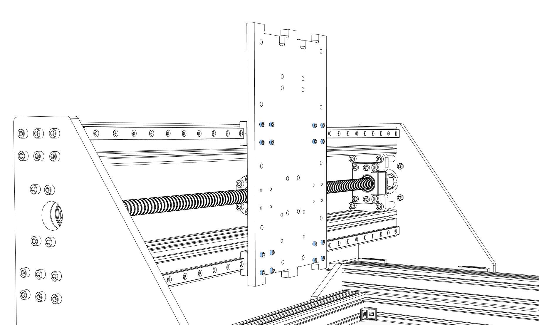
Screw the Z axis backplate to the portal MGN12H blocks (16x M3x14, loose).
-
Move the Z axis to one end, tighten all MGN12H block screws.
-
Utilize the Z axis backplate as a spacer to align the portal rails to one another: Start at one end, tighten the first screw of the lower portal rail (5 Nm max). Move the Z axis backplate one screw and repeat.
-
The Z axis backplate should run freely on the portal. If not, repeat alignment..
-
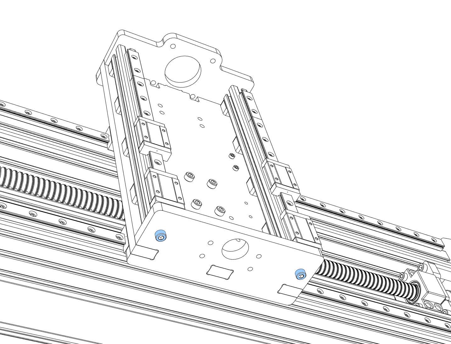
Move the Z axis backplate to the BK12 end, screw the backplate through the “portal nut spacer” (10 mm) to the portal nut holder (4x M5x30, tight). Tighten the screws between nut holder and nut.
-
Move the Z axis backplate to the BF12 end, tighten the screws between the BF12 bearing block and the portal side plate.
-
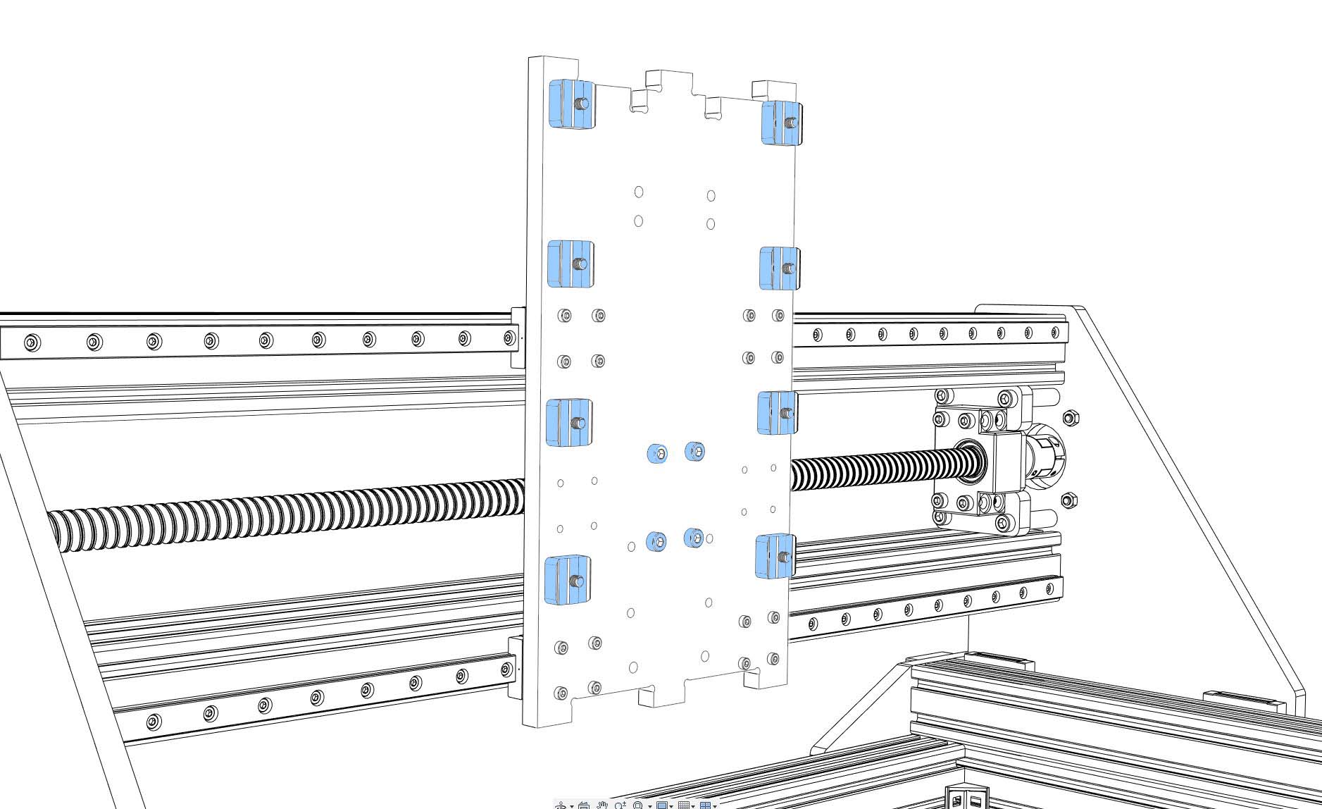
Take the 3D printed Z axis spacers, put 8x M5x22 screws through the Z axis back plate (from the back). Slide the spacers onto the screws, put nuts onto the screws (just a few turns).
-
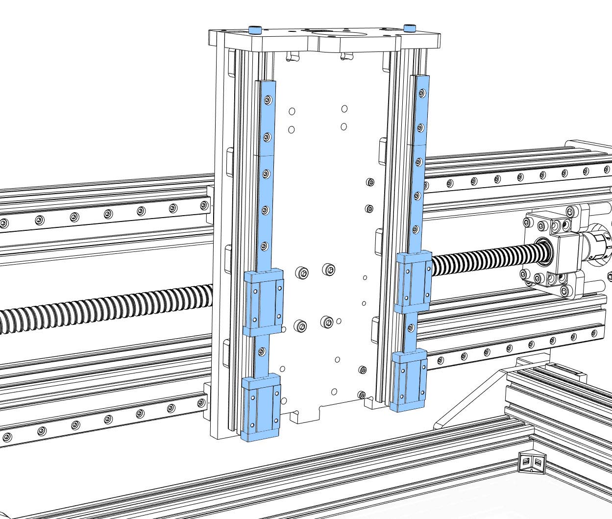
Cut M5 threads into the ends of the two 20x20 profiles (approx. 15 mm depth). Connect the profiles to the Z axis top plate with 2x M5x20, tight (7-8 Nm max). Prepare the MGN12 rails (degrease and lubricate), put M3x8 screws and nuts in every hole of the rails, slide the rails onto the profiles (loose). Each rail has to have two rail blocks (MGN12H). Be careful when sliding the blocks onto the rails (don’t loose balls).
-
Slide the top plate / profiles onto the nuts until the top plate locks into the back plate. Tighten the screws between back plate and profiles (5 Nm max). Be careful not to loose rail blocks (they could fall out downwards).
- Screw the bottom plate onto the back plate (2x M5x20, tight, 7-8 Nm max).
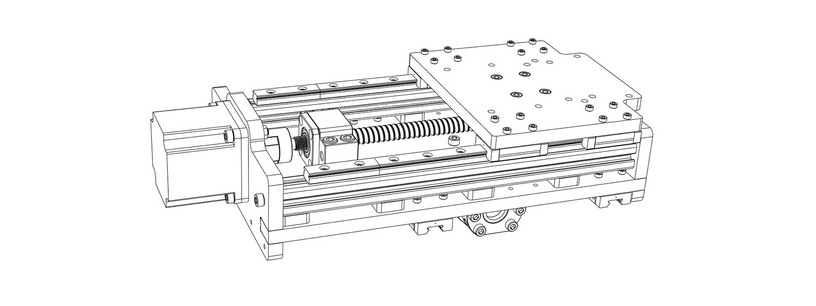
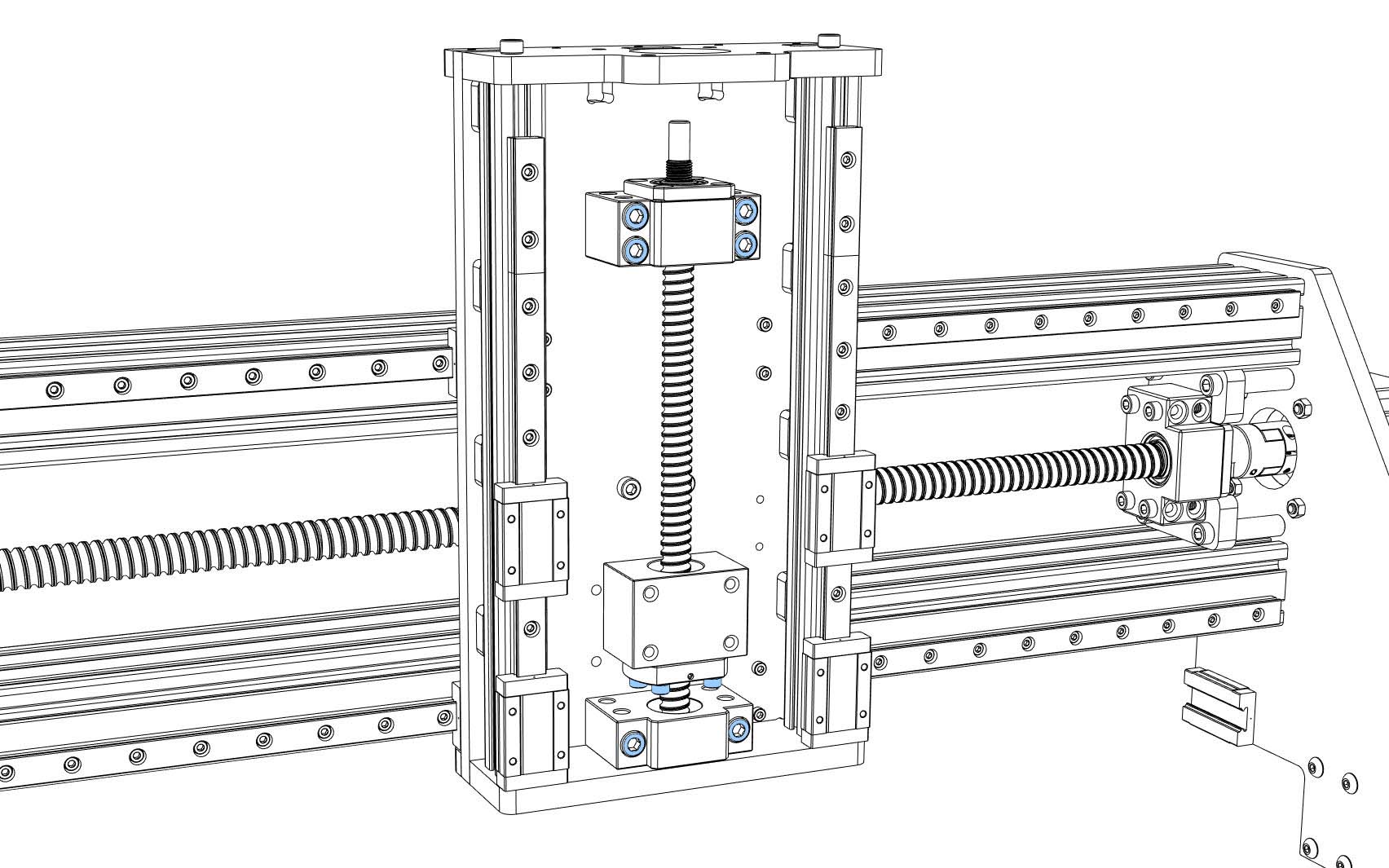
- Prepare the ball screw (SFU1204) (degrease and lubricate). Check if the ball nut is aligned the right way (the end for the screws looks away from the BK10 end). If it is misaligned you should print yourself a removal tool to turn the nuts without loosing balls. Don’t forget the ball nut holder (6x M4x12, loose).
- Put the ball screw onto the fixed bearing block (BK10), lock it with the fine nut.
- Put the ball screw onto the BF10 bearing block.
- Slide the ball screw between the profiles, screw both bearing blocks to the Z axis back plate with 6x M6x40, tight.
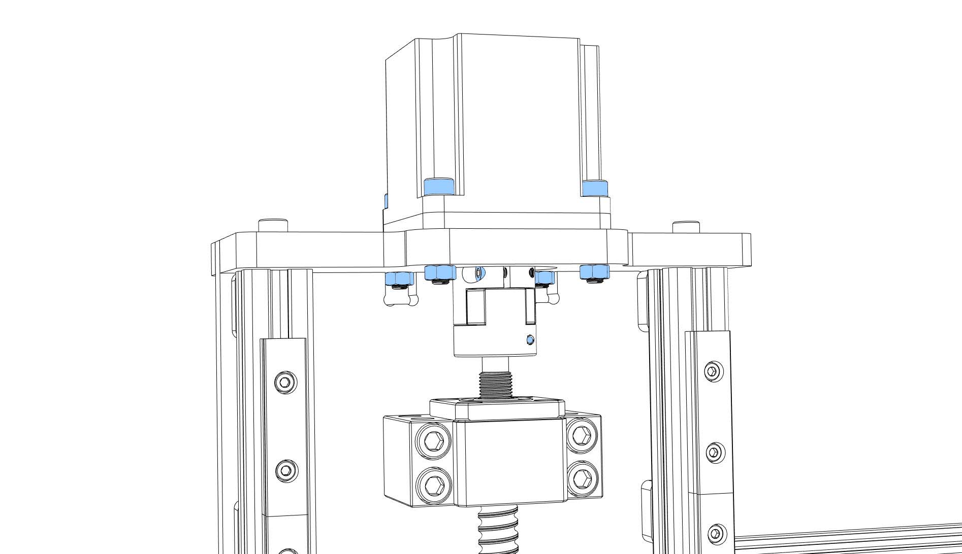
- Slide a coupler onto a NEMA23 motor, tighten the motor shaft side, push the motor through the “Z axis motor spacer” (5 mm) and the top plate onto the ball screw, tighten the coupler. Screw the motor to the top plate (4x M5x25 + nuts, tight).
Aligning the Z axis rails:
-
Align one of Z axis rails: use the 3D printed “Cindymill_Z_Axis_Rail_Alignment_Tool.stl”. Start at one end, align the rail and tighten one screw (5 Nm max). Move the tool one screw and repeat. Use a dial indicator to refine alignment to around 1-2/100 mm deviation.
-
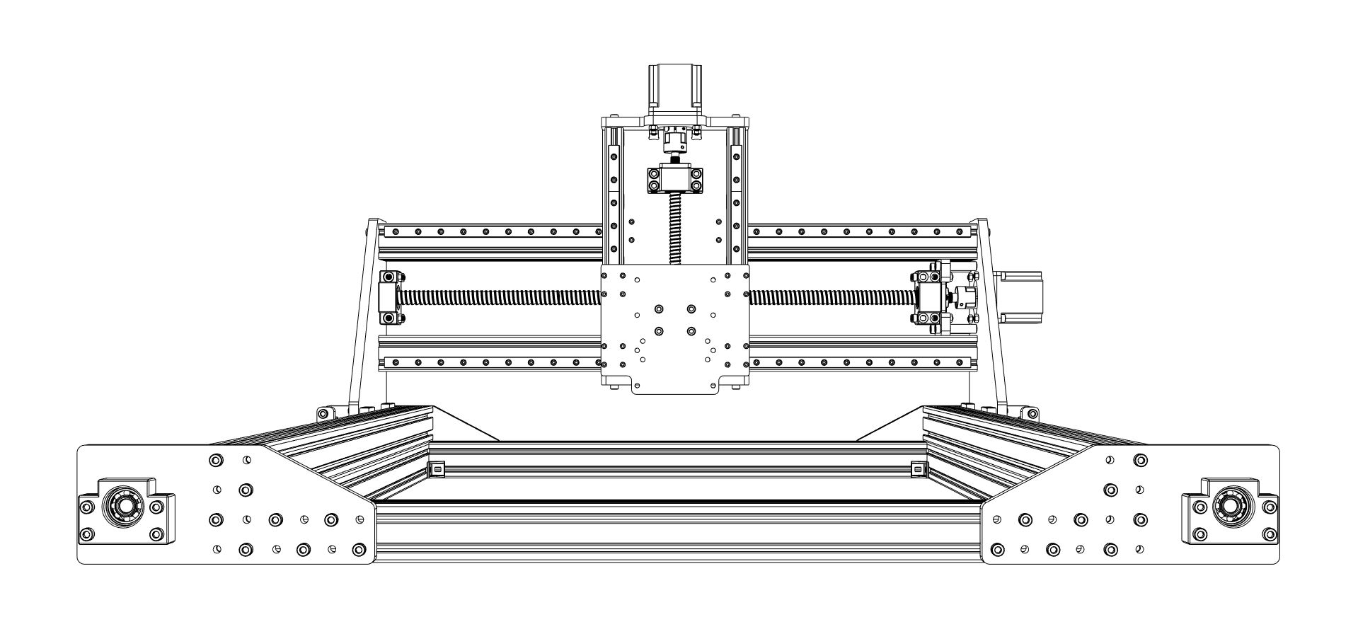
Screw the spindle plate to the Z axis nut holder + spindle plate spacer (3 mm) (4x M5x15, tight).
-
Screw the spindle plate to the Z axis MGN12H blocks (16x M3x14, tight).
-
Utilize the spindle plate as a spacer to align the Z axis rails to one another: Start at one end, tighten the first screw of the second rail (5 Nm max). Move the spindle plate one screw and repeat.
Congratulations, you finished the mechanical part of your build! Grab a bear, take some photos, post them in our facebook group.
If these instructions have helped you, I would appreciate a small donation that will help me maintain this website. Thanks!
![]()
Continue with Electronics.