The Cindymill was born as an upgrade from an Indymill. One of the main reasons to redesign my machine was the lack of rigidity in the indymill, which became really obvious when I started to mill aluminum. So, if you have been thinking of upgrading your Indymill to a Cindymill, then you might be interested in how much the Cindymill is stiffer than the Indymill.
Method
Your machine has to withstand high forces during milling. When the cutter dips into the material, a counterforce acts in the Z direction. When cleaning up pockets or cutting contours, high counterforces occur in the X and Y directions. A common way to measure the stiffness of the machine is to apply a force to the end of the spindle and measure the resulting deflection. In this way, the evasive action of the machine can be simulated when force is applied. This evasion causes various problems, e.g. large deviations between target and actual dimensions in your work piece.
So I built models of the unmodified Indymill portal and the Cindymill portal with similar boundary conditions. Both models are fixed on the side plates at the drill holes for the rail blocks (8 holes per side plate). I removed all drive components since they do not contribute to the rigidity. Then I applied a force of 150 N to the spindle collect (in X, Y, and Z directions) and measured the resulting maximum displacement of the machine.
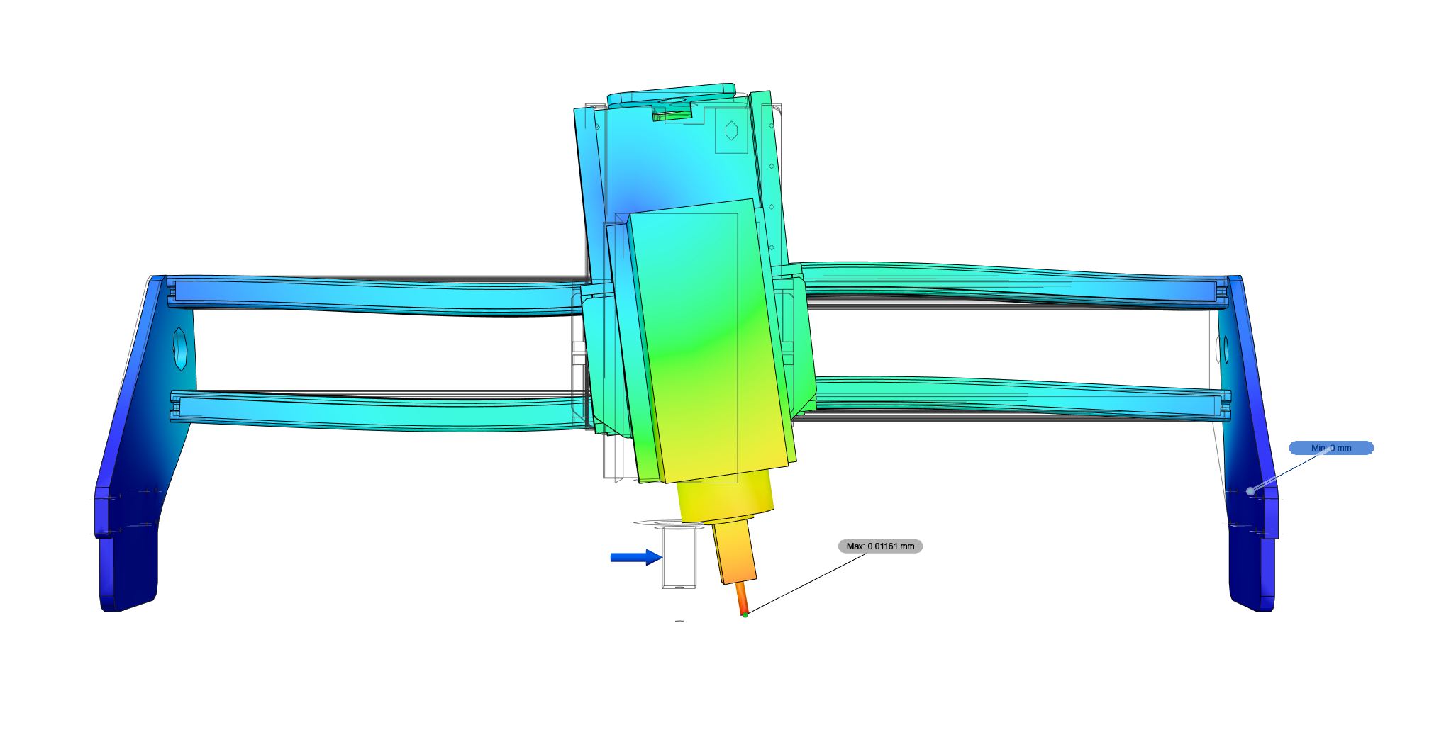
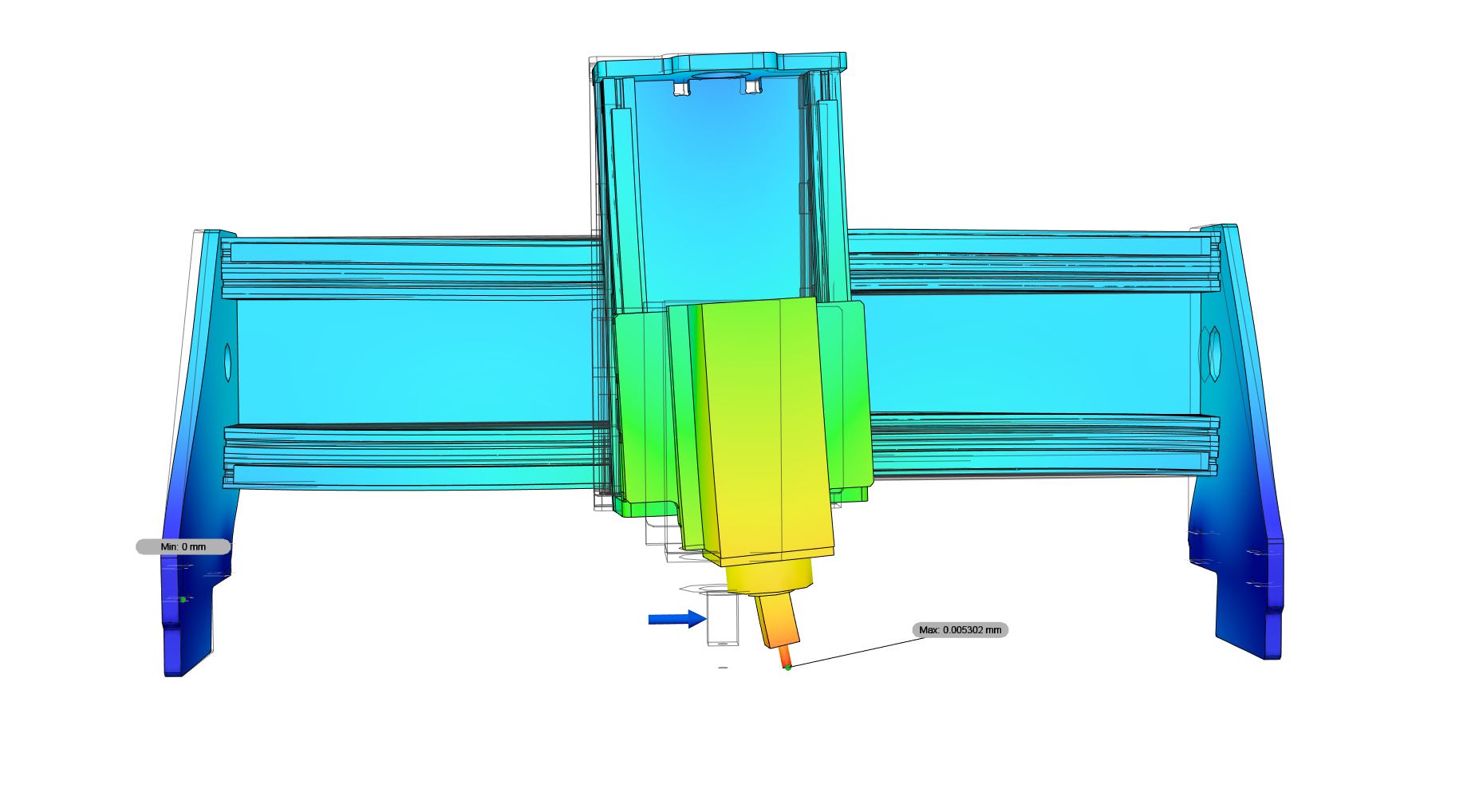
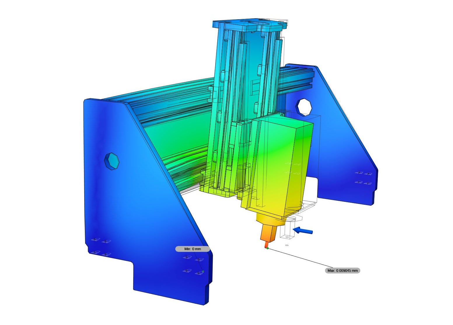
Nomenclature: To avoid confusions: X is the long axis where my portal travels on, Y is the axis where the Z construction travels on along the gantry. Z should be the same for everybody. The animation below shows a force applied in Y direction.
Indymill vs. Indymill + Backplate
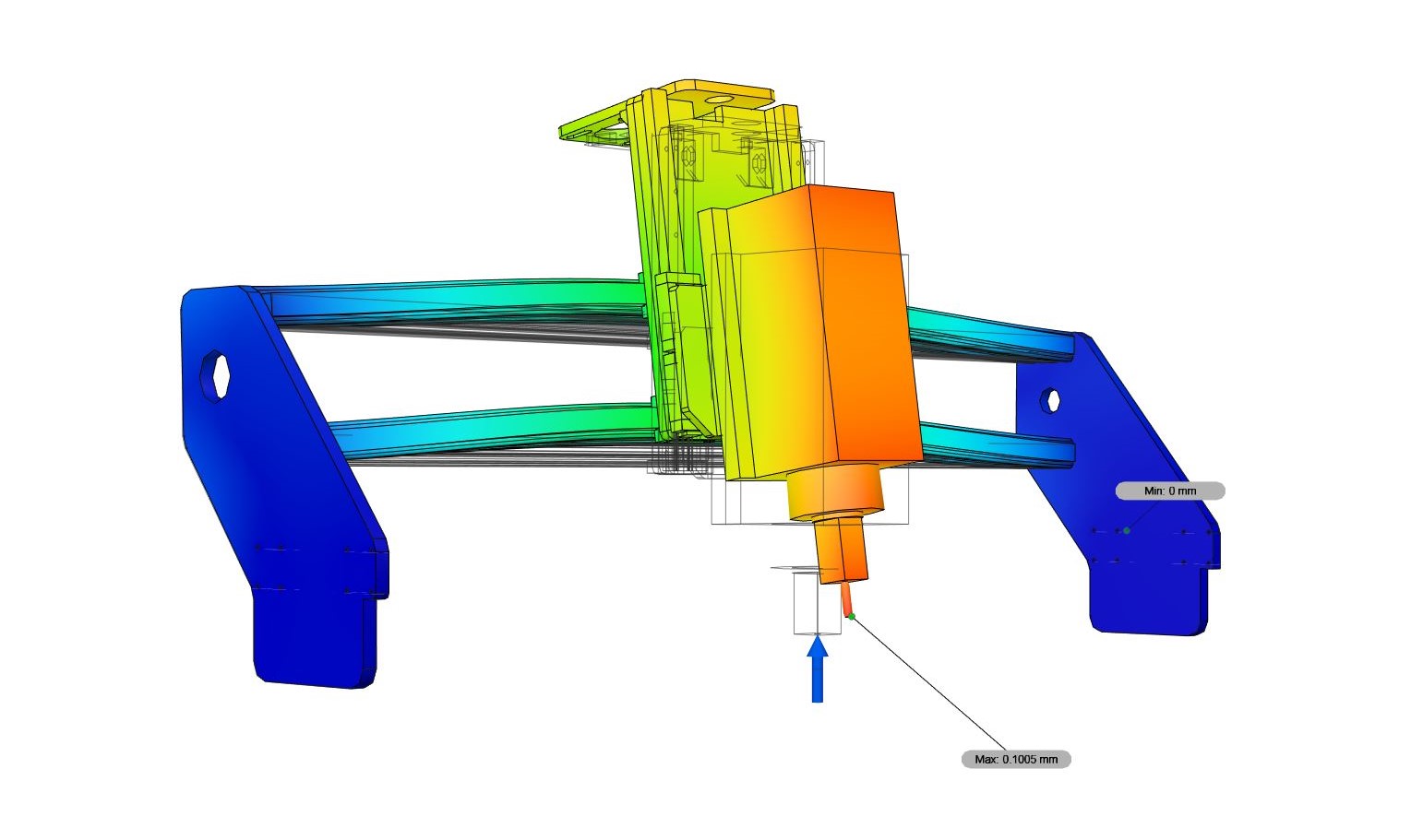
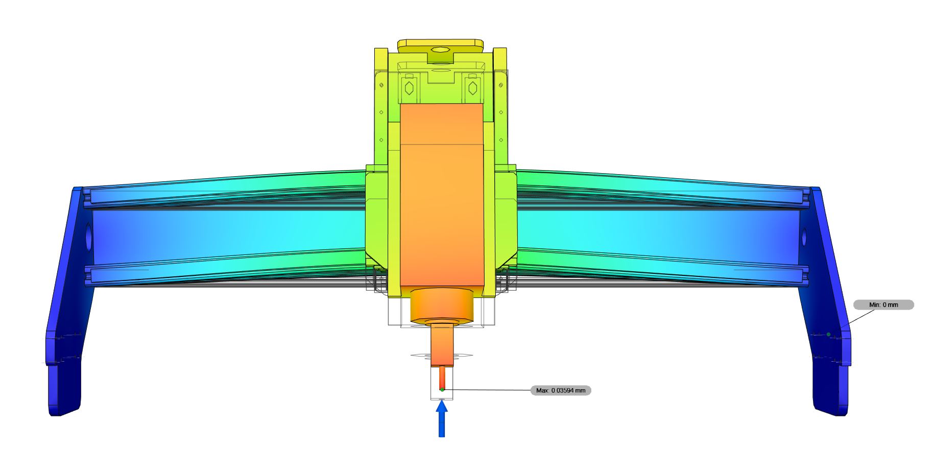
The back plate on the portal is usually underestimated, which also applies to the Indymill project. However, a back plate is essentially important for the stiffness of the portal since it helps to form a box-like construction. To estimate its influence I simulated the Indymill without a back plate (as suggested in the original build) vs. a version with a 5 mm aluminum back plate. The results are promising:
| Force Direction | Displacement Indymill [mm] | Displacement Indymill + Backplate [mm] | Displacement reduced by factor: | |
|---|---|---|---|---|
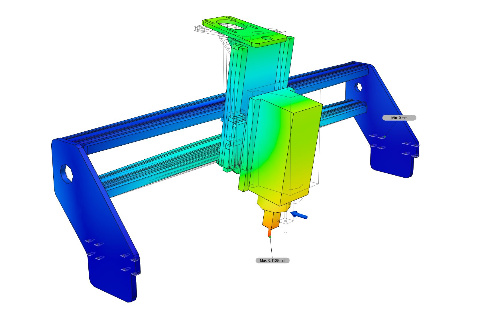
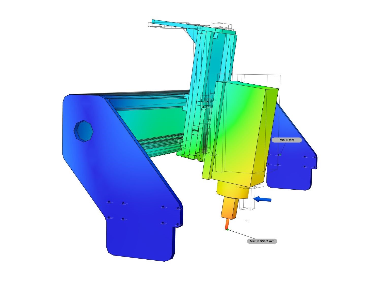
| X | 0,1109 | 0,0407 | 2.72 | |
| Y | 0,0116 | 0,0095 | 1.21 | |
| Z | 0,1005 | 0,0359 | 2.80 |
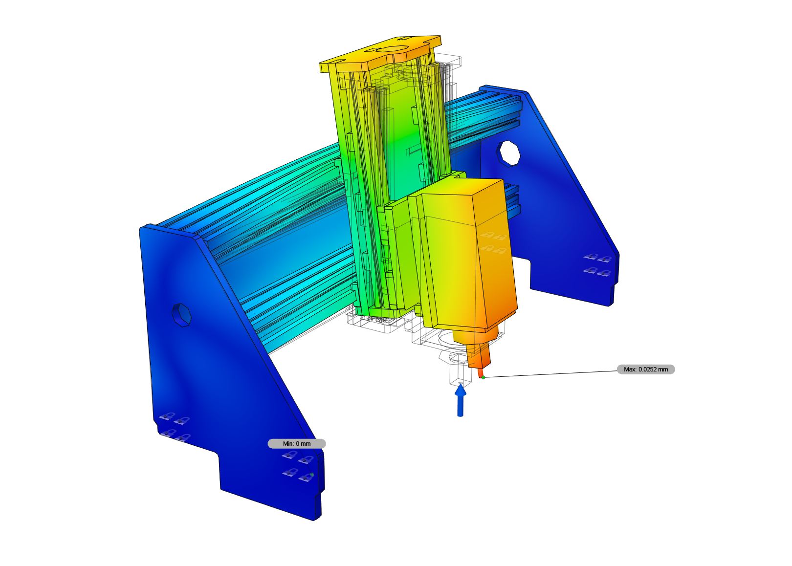
Indymill vs. Cindymill
A second simulation compares the unmodified Indymill to the Cindymill: Upgrading to the Cindymill reduces displacement for similar applied forces by a factor of 2-12, where the greatest influence can be seen for the X axis. I am very happy with this result, even reducing the displacement for the Y axis by a factor of 2 is quite a good value, considering the fact that the Indymill already seems to be relatively stiff in this direction. Note that the stiffness of the Cindymill is much more balanced between the X and Y axes. This should be beneficial for dimensional accuracy.
| Force Direction | Displacement Indymill [mm] | Displacement Cindymill [mm] | Displacement reduced by factor: | |
|---|---|---|---|---|
| X | 0,1109 | 0,0090 | 12,26 | |
| Y | 0,0116 | 0,0053 | 2.19 | |
| Z | 0,1005 | 0,0252 | 3.99 |
Results
A provisional but very simple way to reduce evasive movements somewhat (by a factor of 1-3) on an Indymill is to install a back plate. To really stiffen an Indymill, upgrading to a Cindymill offers a huge advantage. In this way, evasive movements can be reduced by a factor of 2-12.
Happy milling!
Images
X Axis
Indymill
 Indymill + Backplate
 Cindymill
Y Axis
Indymill
Indymill + Backplate
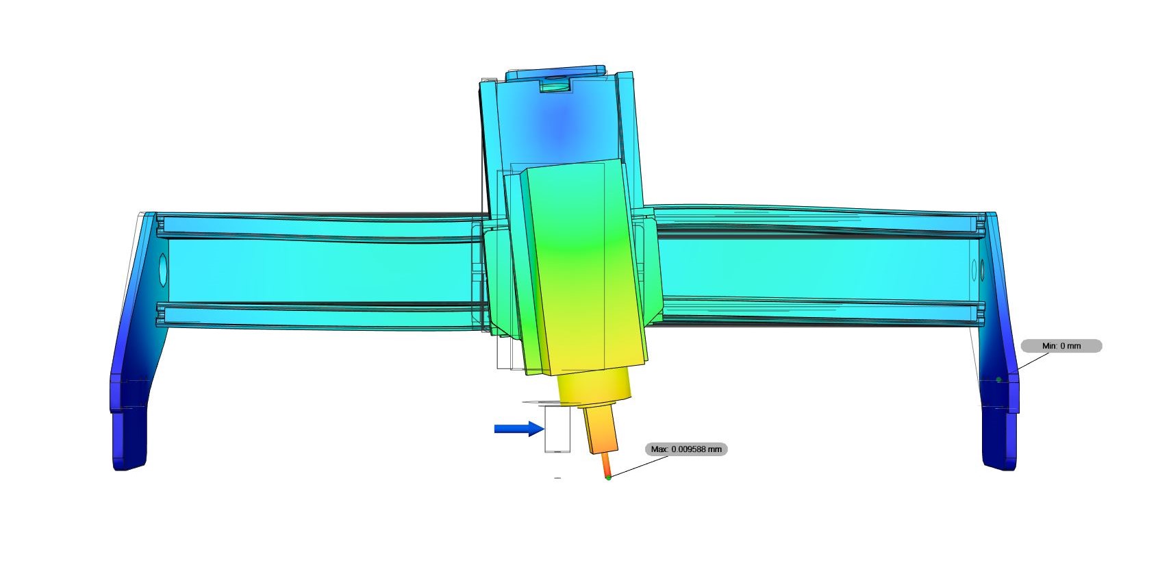 Cindymill
Z Axis
Indymill
Indymill + Backplate
Cindymill